











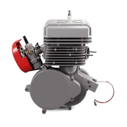
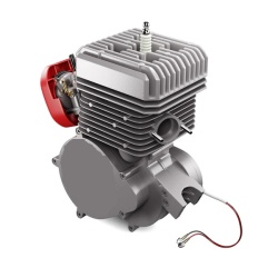
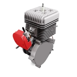
Bicycle cyliner set 100cc 2T (New generation)


Description
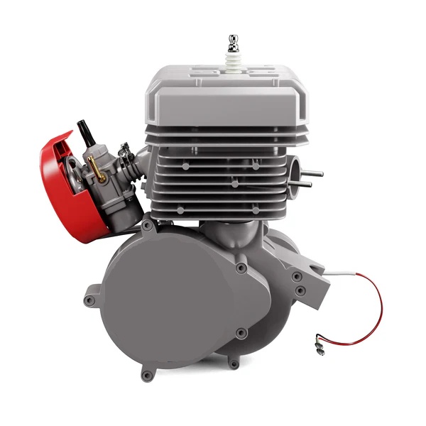
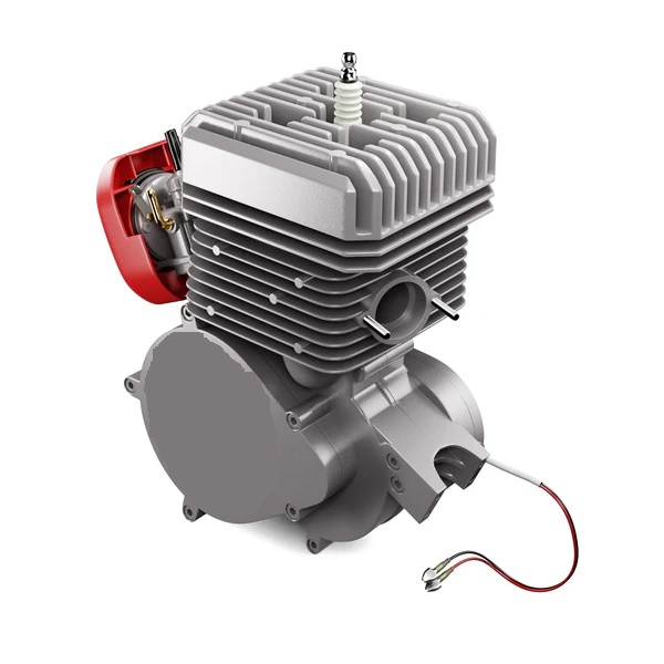
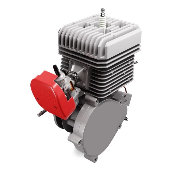
Bike engine kit 100cc 2 STROKE (New generation)
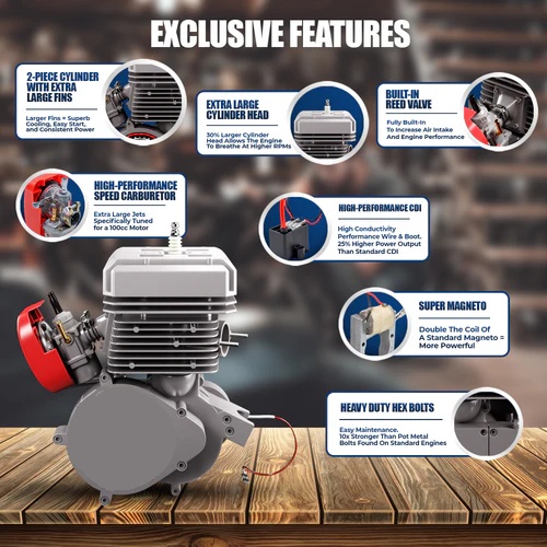
Among the improvements compared to the old generation, we can list:
Carburetor, cylinder, cylinder head and intake manifold.
This kit has a new architecture that improves performance and reliability.
The presented product benefits from a guarantee according to Law no. 449/2003 ONLY IF IT IS MOUNTED IN A SPECIALIZED SERVICE!! If the product is self-assembled, it NO LONGER BENEFITS FROM THE WARRANTY!!
Laws vary from state to state and city to city. For complete legal details, contact your local state and/or city authorities. The end user or installer becomes the vehicle manufacturer and assumes all legal liability.
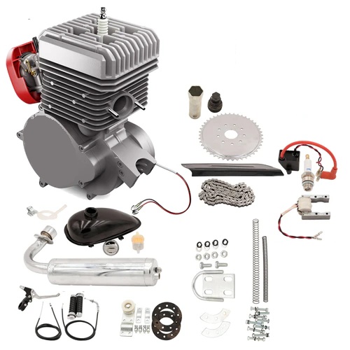
The set consists of:
Engine 3.2 horsepower (piston bore 50mm), cylinder capacity 100cc
Maximum speed up to 80 km/h
carburettor
Exhaust
Gasoline tank 0.8 liters
Pinion Drive with 44 teeth
Scooter transmission chain
Chain tensioner with bearing
Chain protection
Pinion mounting flange
Electronic ignition
Accelerator lever with button
Gasoline valve
Clutch lever with lock
plug
Installation details:
Some technical and mechanical skills are required to install your engine. Some buyers can finish the job in 2 hours while others can take even 2 days. In the end, it doesn't matter how long it takes, you will get great pleasure and satisfaction from completing this project. At the same time, you will understand the system more easily and it will help in its maintenance and operation. Good luck.
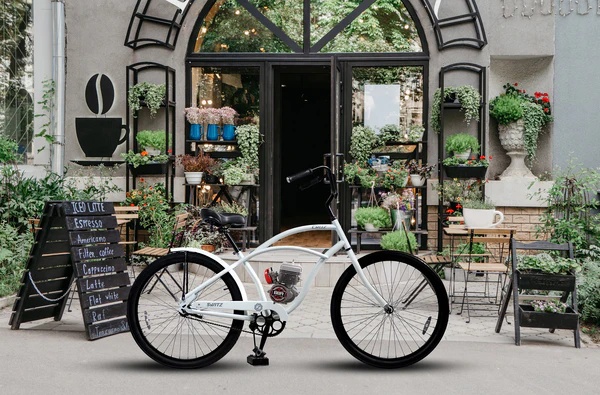
The easiest installation can be done on a standard 26" V-shaped frame with a 25 mm tubular profile. But it can be mounted and adapted to other bikes, but then it must be adapted to the existing conditions. These motors also include adapters for non-standard frames - oval or larger diameters - so that the motor can be attached to the frame. Even if at the beginning during assembly you will spend more time for finishing and adjustments, in return you will ensure thousands of kilometers of operation without operational incidents.
1. Mount the drive pinion on the wheel as follows:
a. Disassemble the bicycle chain
b. Unscrew the nuts that fasten the wheel to the rear fork
c. The wheel is extracted from the fork
d. Disassemble the pinion flange assembly composed of 2 rubber rings and 2 steel crescents
e. Each rubber ring is cut once. Very important! IT WILL ONLY CUT BETWEEN THE HOLES!
f. Proceed to mounting the two rings, each on one side of the spokes, so that the cuts are not in the same direction
g. Mount the external gear pinion by inserting screws (9 pcs) through the pinion, outer rubber ring, through spokes, inner rubber ring, steel crescent, grover washers, flat washers, M6 nuts. In the first phase, all the screws are just fastened without tightening
h. Proceed to tighten them successively without tightening each one to the end. This tightening is done gradually, with equal force until all the fixing screws are tightened at the end
i. The flatness of the pinion is checked. The deviation (inclination) from the vertical plane cannot be greater than 1.5 mm. Otherwise, adjust the screws that determine the deviation
j. Reassemble the wheel taking into account its centering when tightening on the fork.
2. Installing the motor on the metal frame
The motor is installed on the metal frame of the bicycle.
If the frame has a round section and a reduced diameter, then the clamps with which it is equipped from the factory will be used.
In the case of another type of frame, the screw with the extension plate will be used. In general, the vertical bar is of round section so that it will not raise problems for fixing. The extension screw will be used for the regular bar (the front one). A pre-assembly will be done (with the exhaust pipe) in order to determine the optimal position for the engine on the frame. The position of the drive pinion will also be monitored so that the slot in its cover is located in such a way as to allow the installation and operation of the drive chain.
a. After marking the attachment point in front (in the case of the large diameter frame), a hole will be made in the frame so as to allow the attachment screw to pass through the extension.
b. Fasten the fixing plate on the front side
c. Remove the mounting crescent in front of the engine
d. Pass the motor fixing screws through the holes of the fixing plate
e. Insert the grover washers, the flat ones and the M6 nuts, then tighten them with equal force and symmetrically. A final positioning of the engine will be done so that the engine is centered in the frame axis lug.
f. check if the exhaust touches the frame or the flange as well as if it comes into contact with the pedals when mounted. If one of the situations occurs, the engine will be repositioned so as to eliminate these inconveniences.
recommendation
To eliminate vibrations but also the sliding of the engine on the frame, the sleeve can be used
rubber bands. At the same time, damage to the paint on the frame is also avoided.
If necessary, washers or spacers can be inserted between the fixing plate and the frame so that tightening the nuts is easier.
3. Fitting the Exhaust
It is checked if the exhaust touches the frame or the flange, as well as if it comes into contact with the pedals when mounted. If one of the situations occurs, the engine will be repositioned in order to eliminate these inconveniences
Mount the exhaust avoiding contact with the frame, the mounting flanges or the engine. Otherwise, the engine is repositioned. Use the exhaust gasket as well as the flat and grover washers.
4. Mounting the carburetor
Mount the carburetor on the intake pipe. Tighten the fixing screw on the fixing clip from the carburetor - intake pipe connection. The carburetor will be mounted with the air intake pipes down
5. Fixing the controls on the handlebars
Before mounting the cables, their sleeves can be removed and the cables can be greased with vaseline, after which they can be inserted back into their sleeves.
a. Mount the accelerator lever on the right side. Unscrew the cover attached by 2 screws and insert it on the handle of the handlebar. The upper cover contains a pin with the role of fixing and preventing the rotation of the lever support. Check the position of this pin on the handlebar, mark the hole and start drilling with a drill and a drill. After this hole has been given, the upper cover of the lever can be mounted and the two screws are tightened. The free end is fixed to the carburetor cover.
b. Mount the clutch lever on the left side so that both the brake and the rubber handle go in.
The end piece is fixed to the free end of the clutch cable by tightening the screw. It is positioned on the cable so that the control rod no longer has a degree of freedom and does not twist around the axis. If it is not adjusted correctly when the clutch lever is actuated, the engine will not disengage and will remain permanently attached to the gear pinion.
6.Fixing the fuel tank on the frame
The gas tank is fixed on the upper horizontal frame towards the handlebar. As in the case of fixing the motor, rubber sleeves can be used. Tighten the 4 fixing screws, taking into account the clearance of the possible control cables of the bicycle. The supply valve is fixed to the supply pipe together with the sealing gasket. Additional gaskets can be used if the situation requires it.
7. Installation of electronic ignition
The electronic ignition is fixed on the bicycle frame. It will be taken into account that there is enough cable to feed the spark plug from the engine. For fixing, you can use the metal clamp from the set or a quick plastic clamp passed through the holes for fixing the electronic air conditioner. It will be considered to place it as far away from the engine as possible in order to reduce the heat transfer from the engine.
8. Installation and removal of the spark plug
At this moment, remove the spark plug if it is mounted in the engine. This can be removed with the help of the spark plug wrench from the set.
The spark plug will be reassembled ONLY at the end of the installation using these steps:
If the spark plug has a cap at its top, then it is unscrewed and removed to be able to insert the plug into the spark plug head. If this is omitted, the file may be destroyed.
9. Mounting tensioner
Mount the chain tensioner on the horizontal fork, leaving the tension wheel in the minimum position.
Removing the pinion cover
Remove the cover that houses the drive pinion. Undo the 3 screws with the help of a straight screwdriver.
Mounting the chain
Mount the chain on the drive pinion. This is done with the help of the spark plug wrench that turns the engine shaft. At the same time, the chain is wrapped. The other end goes over the wheel pinion but also over the tensioner. In this way, the necessary length of the chain can be estimated. Keep in mind that the locking bolt must also be inserted.
Chain size reduction
The length of the chain is reduced. After it has been marked to the required length and removed from the pinions, proceed to removing the bolts. A 3 mm mandrel, a bushing and a hammer can be used. The Chain Mounting step is repeated. The safety lock is inserted as well as the safety.
Adjusting the tensioner wheel
Raise the tensioning wheel to the required position so that the chain stretches sufficiently but not excessively hard. Tighten the screws fixing the tensioner and the tensioner wheel.
Last checks
Make a few forward and backward movements of the bicycle with the clutch lever pulled in order to see the flatness of the chain with the 2 sprockets but also with the tensioner wheel. If the situation requires it, adjust the components with the problem.
