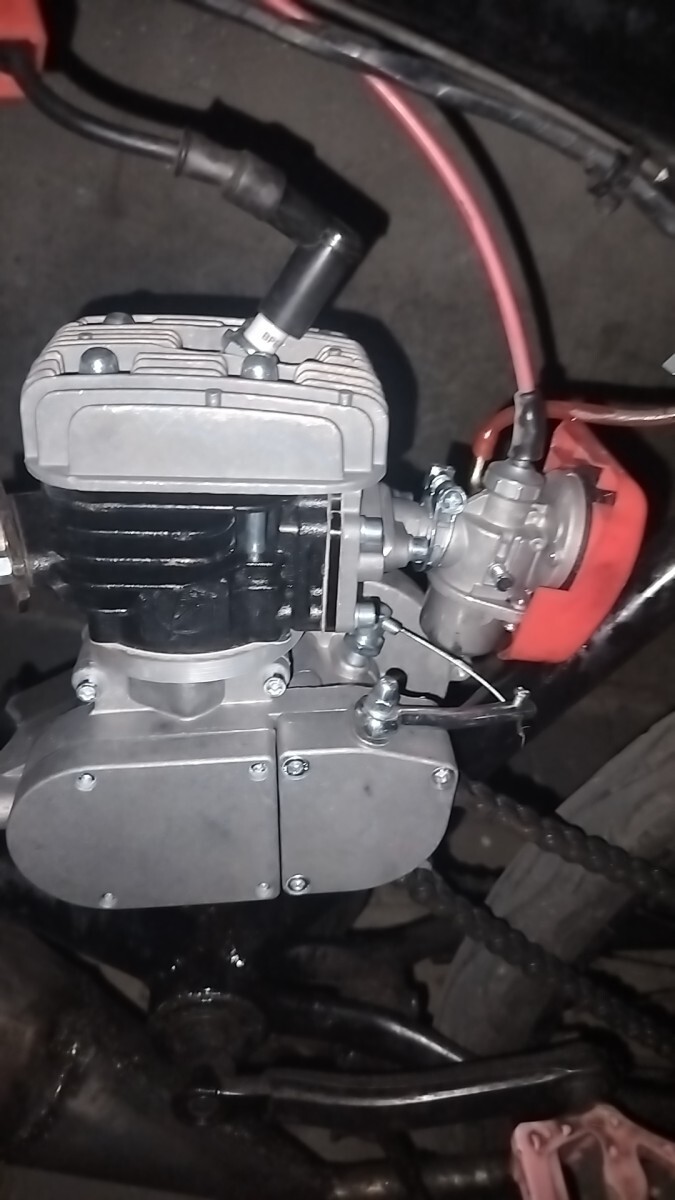


80 cc 2T bike engine kit IRON
Our benefits

Description
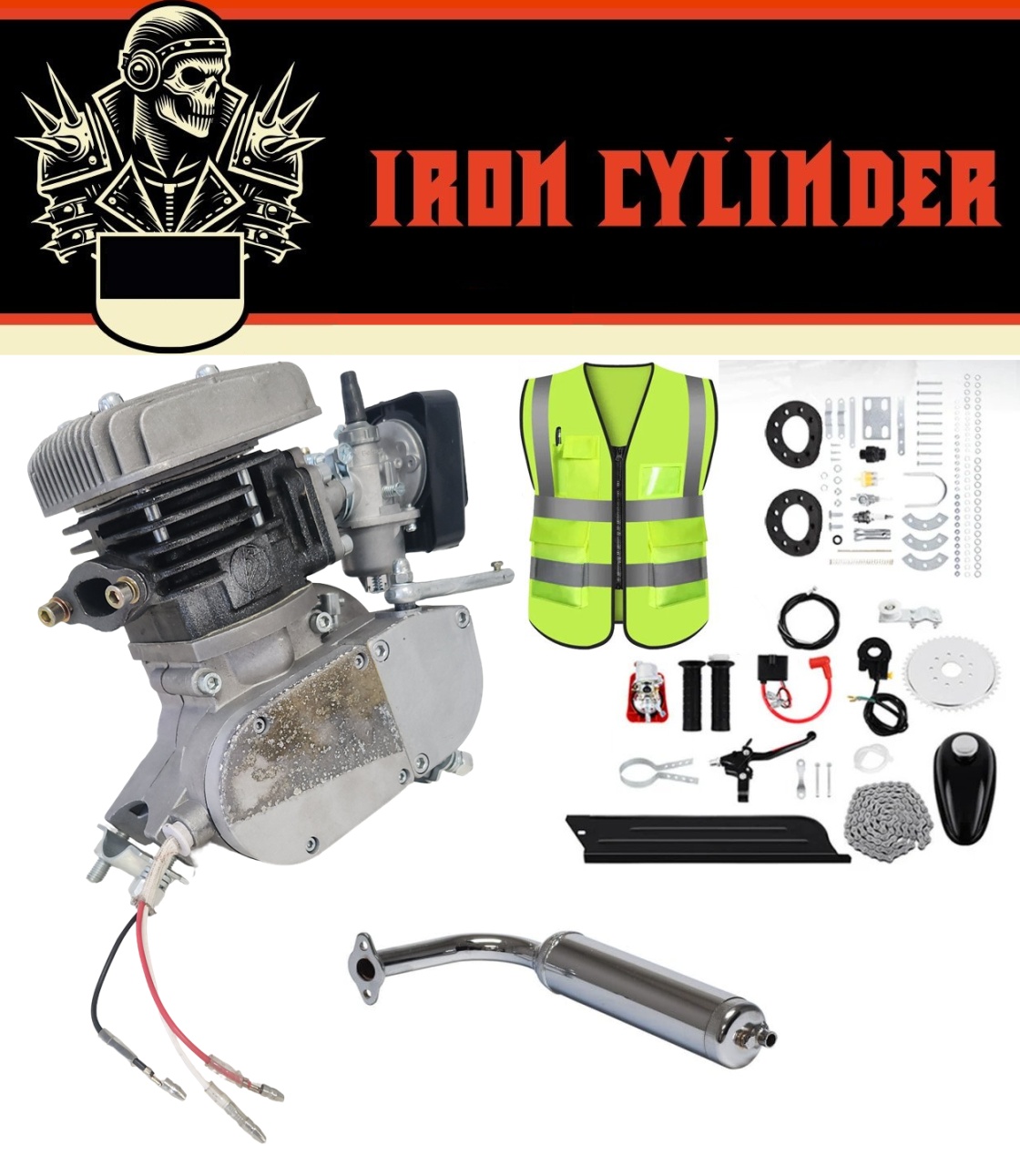
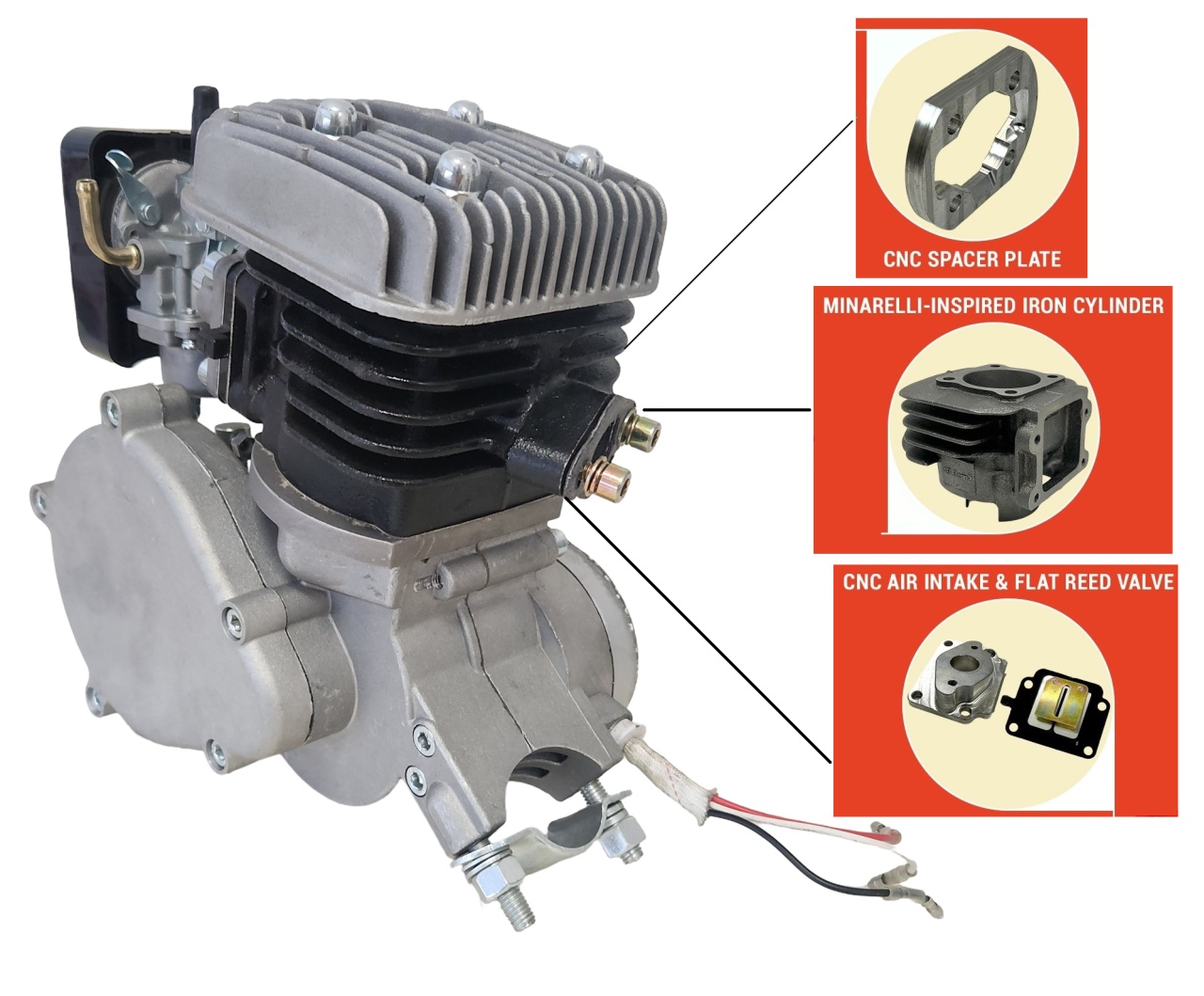
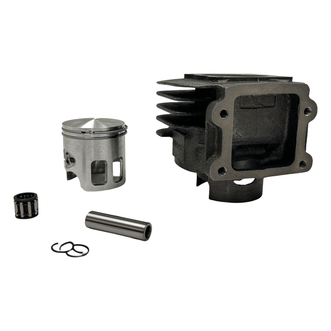
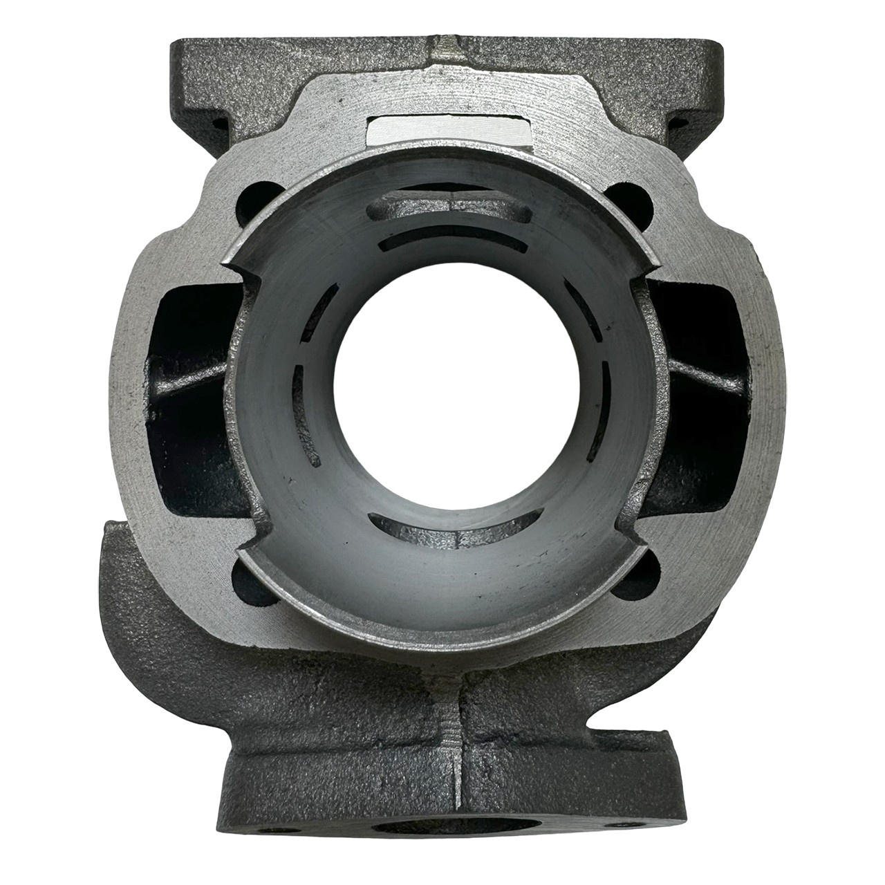
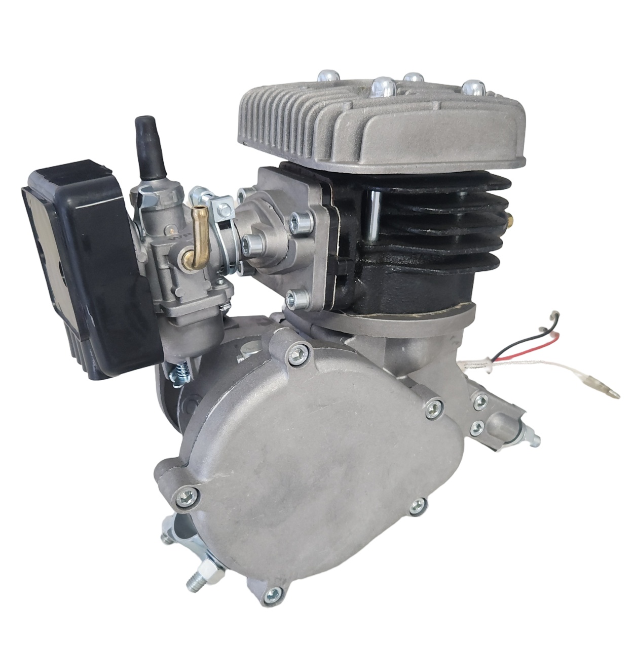
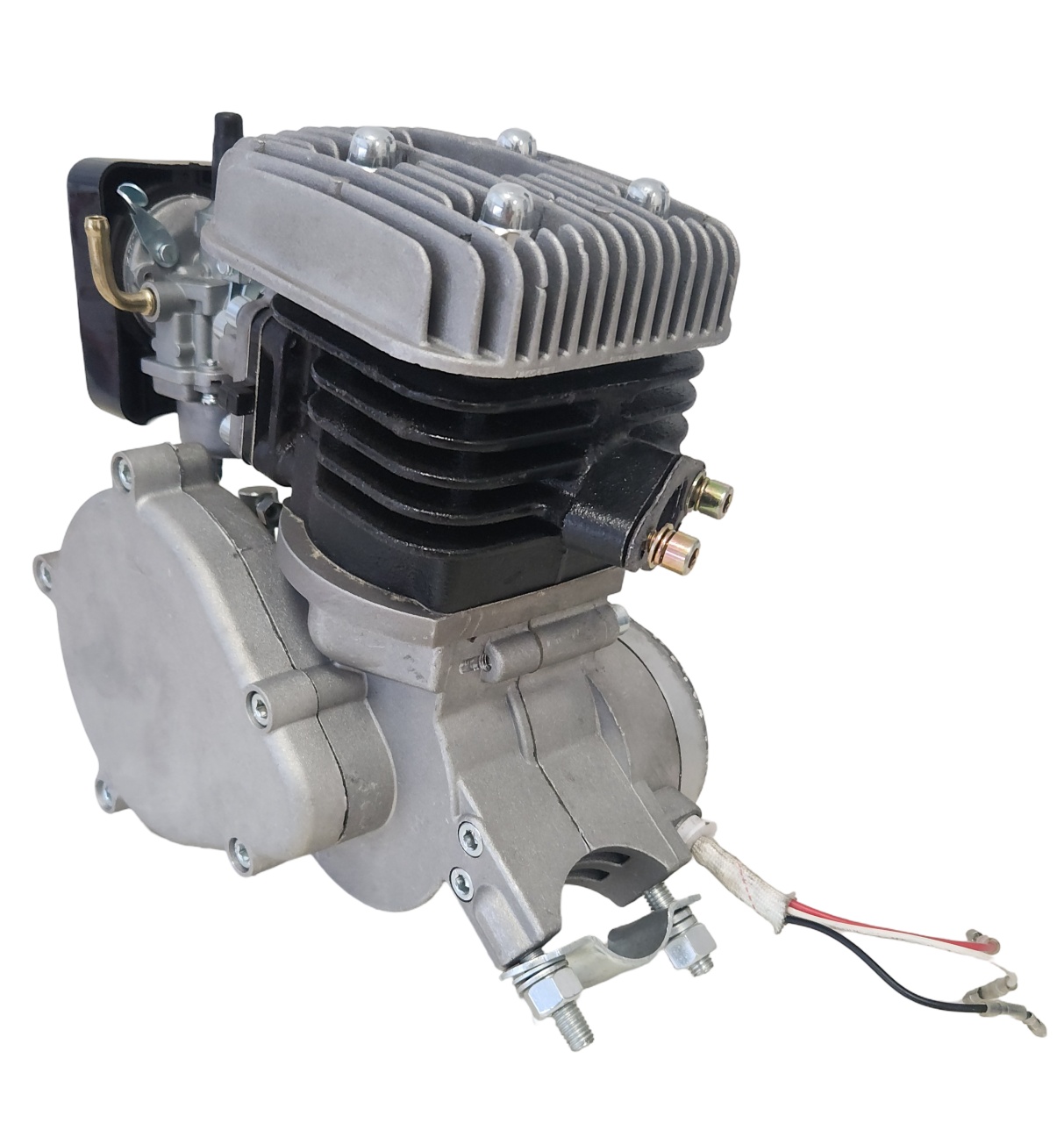
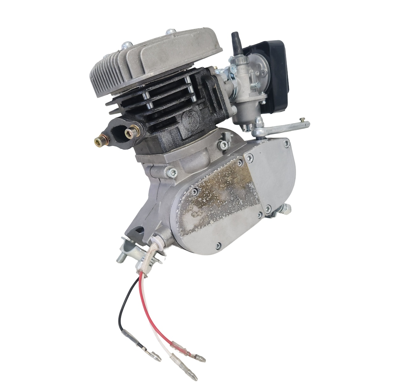
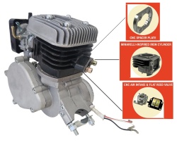
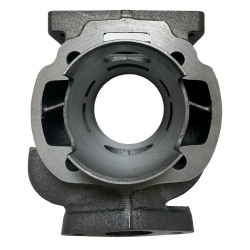
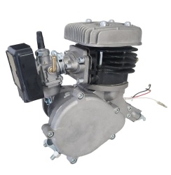
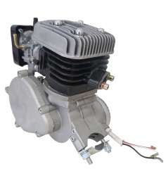
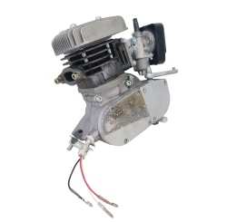
80 cc 2T IRON bike engine kit - a state-of-the-art bike engine that combines advanced engineering with exceptional durability. Inspired by the renowned Minarelli engine design, the IM70 features a robust cast-iron cylinder, ensuring increased longevity and reliable performance for all your motorised cycling adventures.
Additional features 80 cc 2T IRON 80 cc 2T bike engine kit:
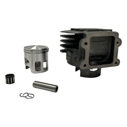
- Cast iron cylinder / bore 47 mm / stroke 40 mm
- Standard power: 6+ hp
- Twin piston with window
- Improved exhaust pipe (48 mm flange distance)
- CDI and high performance magneto
- CNC billet aluminium billet aluminium intake and spacer
- Flat reed valve and intake (harmonicuta)
The presented product is covered by warranty according to Law no. 449/2003 ONLY WHEN ASSEMBLED IN A SPECIALISED SERVICE!!! If the product is self-assembled, it DOES NOT BENEFIT FROM WARRANTY!!!
Laws vary from state to state and city to city. For complete legal details, contact your local state and/or city authorities. The end user or installer becomes the vehicle manufacturer and assumes all legal liability.
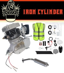
Kit consists of :
- 47mm piston bore 80cc cylinder capacity
- Maximum speed 60km/h
- Carburettor
- Exhaust
- Fuel tank 0,8 Litre
- 44 teeth pinion
- Scooter type drive chain
- Chain tensioner with bearing
- Chain guard
- Pinion clamping flange
- Electronic ignition
- Accelerator lever with push button
- Petrol tap
- Clutch lever with lock
- Spark plug
Assembly details:
Some technical and mechanical skills are required to install your engine. Some buyers can finish the job in 2 hours while others may take up to 2 days. In the end it doesn't matter how long it takes, you will get great pleasure and satisfaction by completing this project. It will also make it easier for you to understand the system and will help you to maintain and operate it. Good luck.
The easiest installation can be done on a standard 26" V-shaped frame with a 25 mm tubular profile. But it can be fitted and adapted to other bikes but then it has to be adapted to the existing conditions. These motors come with adapters for non-standard frames - oval or larger diameters - so that the motor will fit on the frame. Even though you will spend more time on finishing and adjustments at the beginning, you will instead ensure thousands of kilometres of trouble-free operation.
1. Fit the drive sprocket to the wheel as follows:
a. Remove the bicycle chain
b. Unscrew the nuts attaching the wheel to the rear fork
c. Remove the wheel from the fork
d. Unscrew the pinion flange assembly consisting of 2 rubber rings and 2 steel half-rings
e. Cut each rubber ring once. Very important! ONLY CUT BETWEEN THE HOLES!
f. Mount the two rings on either side of the spindles so that the cuts are not in the same direction
g. Mount the external gearing pinion by inserting screws (9 pieces) through the pinion, outer rubber ring, through the lugs, inner rubber ring, steel crescent, grover washers, flat washers, M6 nuts. In the first phase only all bolts are fastened without tightening
h. Then tighten them successively without tightening them all the way. This tightening is done in stages, with equal force until all the fastening bolts are tightened all the way.
i. Check the flatness of the pinion. The deviation (inclination) from the vertical plane must not exceed 1.5 mm. If this is not the case, adjust the screws causing the deviation
j. Refit the wheel in place, ensuring that it is centred when tightened on the fork.
2.Installing the motor on the metal frame
Install the motor on the metal frame of the bicycle.
If the frame is round in cross-section and has a small diameter, use the clamps provided with the frame.
If the frame is of another type, use the bolt with extension plate. Generally the vertical bar is round in cross section so it will not pose any problems for fixing. The extension bolt will be used for the oblique (front) bar. A pre-assembly will be made (with the exhaust pipe) in order to determine the optimum position for the motor on the frame. The position of the drive sprocket will also be tracked so that the slot in the drive sprocket cover is positioned to allow the gear chain to be fitted and operated.
a. After marking the front clamping point (in case of large diameter frame), a hole shall be drilled in the frame so as to allow the clamping bolt to pass through the extrusion.
b. Clamp the front clamping plate
c. Remove the motor front clamping half-moon
d. Pass the motor mounting bolts through the holes in the mounting plate
e. Insert the grover, spade and M6 nuts and then proceed to tighten them with equal and symmetrical force. Make a final positioning of the motor in such a way that the motor is centred in the frame axle lug.
f. Check that the exhaust is touching the frame or flange and that the mounted exhaust is in contact with the pedals. If either of these situations occurs, the engine will be repositioned to eliminate these inconveniences.
Recommendations
In order to eliminate vibrations and motor slippage on the frame, rubber grips can be used. This also avoids damaging the paint on the frame.
If necessary, washers or spacers can be inserted between the mounting plate and the frame to make it easier to tighten the nuts.
Fitting the exhaust
Check that the exhaust is in contact with the frame or flange and that the mounted exhaust is in contact with the pedals. If it does, the engine will be repositioned to eliminate these inconveniences
Mount the exhaust, avoiding contact with the frame, the clamps or the motor. Otherwise, the engine must be repositioned. Use the exhaust gas gasket as well as the flat and grover air bubbles.
Fitting the carburettor
Mount the carburettor on the intake pipe. Tighten the retaining screw on the retaining clip at the carburettor - intake pipe connection. Mount the carburettor with the air intake pipes downwards